Slot Geometry Decoded: Keyhole, J-Slot, Wide U-Slot, and Continuous Rims
Slot geometry affects segment interruption and debris paths, but cannot determine suitability on its own.
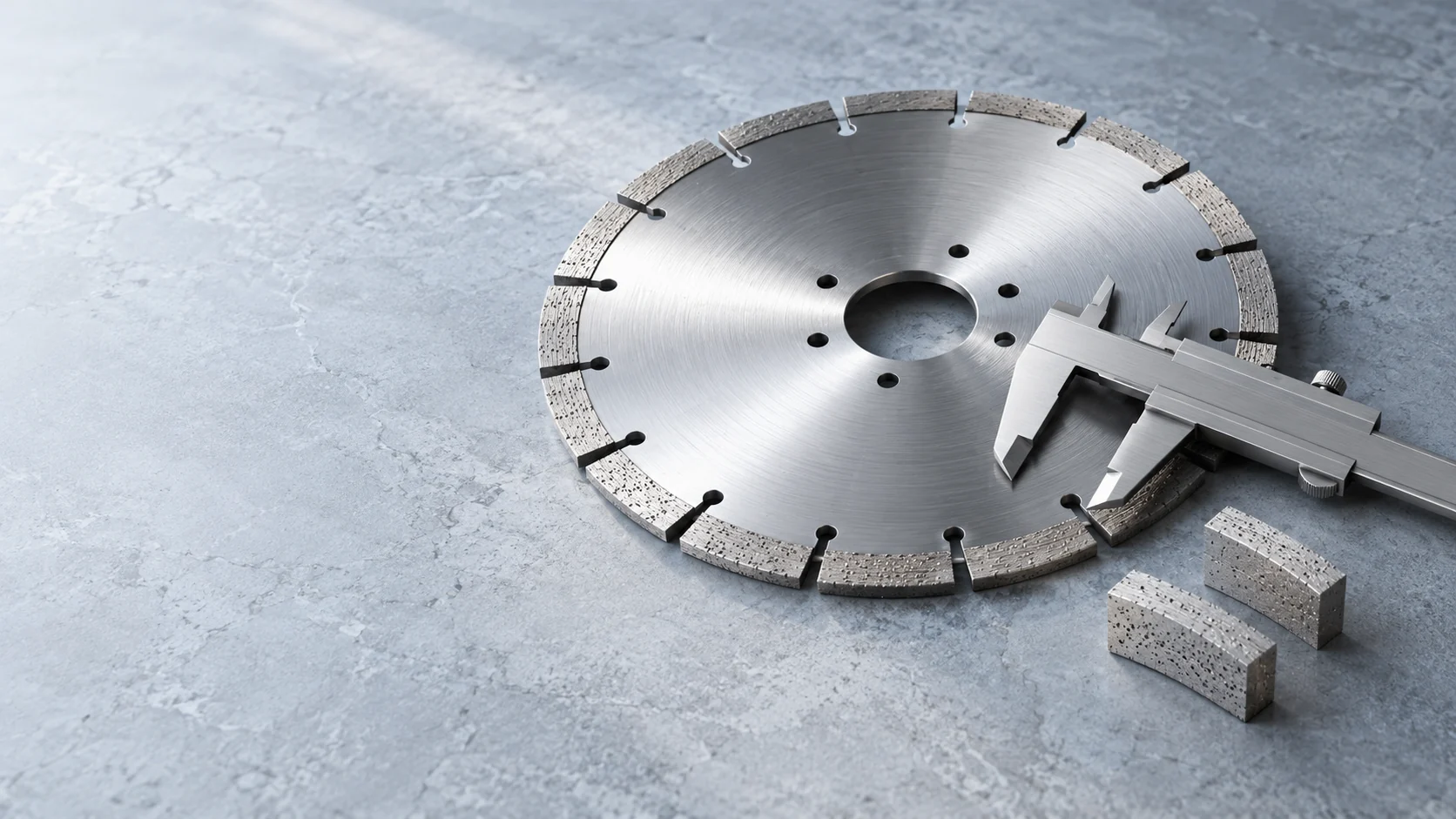
Selection guidance depends on material, machine, and working conditions. Confirm RPM, feed, and cooling against tool markings and machine instructions, then trial the target material.
Content compiled by ADAMA CUT. Compare product specifications with the original Hubei Qianzhao Diamond Tools catalog; verify general process guidance on the actual machine and material. Source catalog PDF
Start with the full design
Straight, J-shaped, keyhole, wide U-shaped slots, and continuous rims are geometry options, not a ranking by material. Check the segment formulation, diameter, kerf, core, material, depth of cut, and cooling together. Slot shape alone does not guarantee debris clearance or fatigue life.
Compare interrupted rims
A wider opening may leave more room for debris; a narrower opening changes how segments enter the cut. Keyhole and curved slots depend on the detailed core design. Slot depth, segment count and size, water direction, and machine condition all matter. Ask for the model drawing or specification.
Compare continuous rims
A continuous rim engages the material differently from a segmented blade, but edge quality still depends on material, grit, tool condition, clamping, and feed. It is not suitable for every tile by definition, and J-slots are not mandatory for sintered slabs.
RFQ and trial
Supply material, thickness, cut depth, machine, diameter and arbor, wet/dry method, and photos of the current cut. Ask the manufacturer to explain each candidate’s limits, then compare edge quality, debris removal, and abnormal tool behavior under matched conditions.
Compiled by ADAMA CUT. The source catalog and industry references below do not imply endorsement or certification of our products. Follow the specific tool markings and machine instructions, then trial the target material.
Blade Peripheral Speed & RPM Conversion
Enter blade diameter and spindle RPM to calculate peripheral speed: v = π × D(mm) × n(rpm) / 60000.
Converts only the target you enter; this tool does not recommend a material speed.
—
A calculation is not a safe-speed or fitment approval. Do not exceed the tool-marked maximum RPM or machine limits. Confirm material, cooling, and feed conditions with a trial cut.
Need the Complete Technical Spec Sheet Offline?
View the original Hubei Qianzhao Diamond Tools Co., Ltd. catalog. ADAMA CUT is its overseas business brand; verify specifications against the source page and confirmed documents.